Introduction
This page provides information in regards to the RS232 standard often used in serial communications.
Signal Levels
The following applies to all RS232 signals, TxD, Rxd, CTS, RTS, etc.
Logic 1 = -3V to -15V
Logic 0 = +3V to +15V
Undefined = -3V to 3V

Idle State
The idle state of a RS232 Transmit pin (TxD) is a logic 1 (-3V to -15V).
RS232 DTE & DCE
DTE = Data Terminal Equipment, i.e. PC. DTEs should be fitted with Male connectors.
DCE = Data Communications Equipment, i.e. MODEM. DCEs should be fitted with Female connectors.

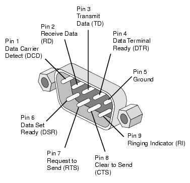
RS232 Serial Port Pinouts
The most common RS232 serial connectors are DB9 and DB25.
DB9 Pin
| DB25 Pin | Acronym | Full name | Direction (DTE) | Meaning |
|---|
|
1
|
8
|
DCD
|
Data Carrier Detect |
DTE <-- DCE
|
Modem connected to another |
|
2
|
3
|
RxD
|
Receive Data |
DTE <-- DCE
|
Receives bytes into PC (DCE to DTE) |
|
3
|
2
|
TxD
|
Transmit Data |
DTE --> DCE
|
Transmits bytes out of PC (DTE to DCE) |
|
4
|
20
|
DTR
|
Data Terminal Ready |
DTE --> DCE
|
I'm ready to communicate (DTE) |
|
5
|
7
|
SG
|
Signal Ground |
|
|
|
6
|
6
|
DSR
|
Data Set Ready |
DTE <-- DCE
|
I'm ready to communicate (DCE) |
|
7
|
4
|
RTS
|
Request To Send |
DTE --> DCE
|
RTS/CTS flow control (DTE to DCE) |
|
8
|
5
|
CTS
|
Clear To Send |
DTE <-- DCE
|
RTS/CTS flow control (DCE to DTE) |
|
9
|
22
|
RI
|
Ring Indicator |
DTE <-- DCE
|
Telephone line ringing |


RS232 Serial Cables
The following have been copied from http://www.bb-elec.com/Learning-Center/Serial-Connectivity.aspx
DTE - DCE (Standard Cable)


DCE - DCE or DTE - DTE (Null Modem Cable)


RS232 Listener Cable
A simple listener can be made for half duplex systems (NOTE: This listener cable will NOT work on full duplex systems).
The below circuit relies on pull down resistors inside the listener RS232 port. If this is not the case then large value resistors (e.g. 4k7Ω) can be fitted in parallel with the diodes.

Simple listener that uses two serial ports, one to receive data transmitted from the PC and one to receive data transmitted from the device.

References
http://en.wikipedia.org/wiki/RS-232
http://en.wikipedia.org/wiki/Serial_port
http://www.aggsoft.com/rs232-pinout-cable/pinout-and-signal.htm
http://www.bb-elec.com/Learning-Center/Serial-Connectivity.aspx
Views: 
Comments (0)
You don't have permission to comment on this page.