Introduction
This page provides information in regards to 2JZ-GTE VVTi engine wiring as found in the Japanese JZA80 Toyota Supra.
If you've found my work helpful and would like to donate a beer! PayPal.Me/wilbo666wiring
JZA80 Toyota Supra 2JZ-GTE VVTi Engine ECU Part Numbers
| Toyota Part Number |
Dates |
Transmission |
| 89661‑14830 | 09/1997 to 07/2002 |
Manual Transmission |
| 89661‑14820 | 09/1997 to 07/2002 |
Automatic Transmission |
Note that the later revision engine ECU has an engine immobilizer inbuilt to the engine ECU.
JZA80 Toyota Supra 2JZ-GTE VVTi Engine ECU Pinout

| Plug | Pin | Symbol | Definition | Input / Output | What | Why | How | Link |
| B74 | 1 | #30 | No. 3 Injector | Output | This pin is used to control the No.3 fuel injector. | The fuel injectors are electronically controlled by the engine ECU. | This pin is connected to Ground inside the ECU as required to turn the fuel injector ON. The fuel injector should be wired with one side of the solenoid connected to battery voltage (Ignition switched) and one side of the fuel injector connected to this ECU pin. | |
| B74 | 2 | #40 | Cyl 4 Injector Driver | Output | This pin is used to control the No.4 fuel injector. | The fuel injectors are electronically controlled by the engine ECU. | This pin is connected to Ground inside the ECU as required to turn the fuel injector ON. The fuel injector should be wired with one side of the solenoid connected to battery voltage (Ignition switched) and one side of the fuel injector connected to this ECU pin. | |
| B74 | 3 | #50 | Cyl 5 Injector Driver | Output | This pin is used to control the No.5 fuel injector. | The fuel injectors are electronically controlled by the engine ECU. | This pin is connected to Ground inside the ECU as required to turn the fuel injector ON. The fuel injector should be wired with one side of the solenoid connected to battery voltage (Ignition switched) and one side of the fuel injector connected to this ECU pin. | |
| B74 | 4 | #60 | Cyl 6 Injector Driver | Output | This pin is used to control the No.6 fuel injector. | The fuel injectors are electronically controlled by the engine ECU. | This pin is connected to Ground inside the ECU as required to turn the fuel injector ON. The fuel injector should be wired with one side of the solenoid connected to battery voltage (Ignition switched) and one side of the fuel injector connected to this ECU pin. | |
| B74 | 5 | VSV1 | Intake Air Bypass Valve Vacuum Switching Valve | Output | This pin is used to control the VSV which is used to open / close the Intake Air Bypass Valve that is a component of the sequential turbo system. | The Intake Air Control Valve allows pressurised air to exit the rear turbocharger allowing it to fully come online as part of the sequential turbo system. | This pin is connected to Ground inside the ECU as required to turn the Intake Air Control Valve VSV ON allowing pressurised intake air to open the Intake Air Control Valve. One side of the VSV should be wired to this pin and one side of VSV should be wired to battery voltage (Main EFI Relay switched). | |
| B74 | 6 | / | / | / | / | / | / | |
| B74 | 7 | M- | ETCS-i Motor | Output | This pin is used to control the electronic throttle control motor. | The throttle is controlled by an electric motor that is controlled by the engine ECU. Having the throttle controlled by the engine ECU allows idle speed control, traction control, etc to be built directly into the engine ECU simplifying the system. | This pin is used together with the M+ pin to power the electric motor to allow it to be opened and closed by the engine ECU as required. The ETCS-i clutch must be engaged for the electric motor to be able to open or close the throttle. The M+ and M- pins are triggered by the engine ECU in a PWM fashion. | |
| B74 | 8 | M+ | ETCS-i Motor | Output | This pin is used to control the electronic throttle control motor. | The throttle is controlled by an electric motor that is controlled by the engine ECU. Having the throttle controlled by the engine ECU allows idle speed control, traction control, etc to be built directly into the engine ECU simplifying the system. | This pin is used together with the M- pin to power the electric motor to allow it to be opened and closed by the engine ECU as required. The ETCS-i clutch must be engaged for the electric motor to be able to open or close the throttle. The M+ and M- pins are triggered by the engine ECU in a PWM fashion. | |
| B74 | 9 | ME01 | ETCS-i Ground | Input | Ground | Used to supply a Ground path to allow current to flow. A separate ground is used for the electronic throttle control system to reduce noise introduced between systems. | This pin connects to Ground or the battery negative via the Intake Manifold Rear Earth. | |
| B74 | 10 | G2 | Intake Camshaft Position Sensor | Input | This pin is used to detect the location of the intake camshaft. | The engine ECU needs to know the position of the intake camshaft for variable intake camshaft position control, the camshaft position sensor provides this information. | This pin connects to the camshaft position sensor located to the rear of the intake side of the engine head which outputs 3 pulse (reluctor pulses) per camshaft revolution. | |
| B74 | 11 | IGT | Ignition Trigger Cyl 1 & Cyl 6 | Output | This pin is used to control the ignition for cylinders 1 & 6. | The ignition timing is electronically controlled by the engine ECU. | This pin is connected to +5V inside the engine ECU as required to trigger engine ignition. Ignition is triggered on the high (+5V) to low (0V) transition. | |
| B74 | 12 | IGT2 | Ignition Trigger Cyl 5 & Cyl 2 | Output | This pin is used to control the ignition for cylinders 5 & 2. | The ignition timing is electronically controlled by the engine ECU. | This pin is connected to +5V inside the engine ECU as required to trigger engine ignition. Ignition is triggered on the high (+5V) to low (0V) transition. | |
| B74 | 13 | IGT3 | Ignition Trigger Cyl 3 & Cyl 4 | Output | This pin is used to control the ignition for cylinders 3 & 4. | The ignition timing is electronically controlled by the engine ECU. | This pin is connected to +5V inside the engine ECU as required to trigger engine ignition. Ignition is triggered on the high (+5V) to low (0V) transition. | |
| B74 | 14 | / | / | / | / | / | / | |
| B74 | 15 | PMC | Pressure Modulation Control (Wastegate) Vacuum Switching Valve | Output | This pin is used to control the VSV which controls the turbo wastegate on the front turbo. This VSV allows the engine ECU to attempt to control boost pressure. | The Wastegate Control Valve allows exhaust gas to pre-spool the rear turbocharger prior to it coming online as part of the sequential turbo system. | This pin is connected to Ground inside the ECU as required to turn the Pressure Modulation Control valve which is more commonly called the wastegate control valve ON allowing pressurised intake air to be diverted away from the mechanical wastegate actuator. When this VSV is ON the mechanical wastegate actuator will not operate and the wastegate will not open, this will result in a very large amount of boost pressure being generated by the turbochargers. One side of the VSV should be wired to this pin and one side of VSV should be wired to battery voltage (Main EFI Relay switched). | |
| B74 | 16 | / | / | / | / | / | / | |
| B74 | 17 | OCV- | VVTi Solenoid | Output | This pin is used to control the solenoid that controls position of the intake camshaft. | Controlling the position of the intake camshaft can be used to improve performance and fuel economy. | This pin is used together with the OCV+ pin to power a solenoid that allows engine oil pressure to be used to vary the position of the intake camshaft. The OCV+ and OCV- pins are triggered by the engine ECU in a PWM fashion. | |
| B74 | 18 | OCV+ | VVTi Solenoid | Output | This pin is used to control the solenoid that controls position of the intake camshaft. | Controlling the position of the intake camshaft can be used to improve performance and fuel economy. | This pin is used together with the OCV- pin to power a solenoid that allows engine oil pressure to be used to vary the position of the intake camshaft. The OCV+ and OCV- pins are triggered by the engine ECU in a PWM fashion. | |
| B74 | 19 | CL- | ETCS-i Clutch | Output | This pin is used to control the electronic throttle control clutch. | The throttle is controlled by an electric motor that is controlled by the engine ECU however there is a clutch that is controlled by the engine ECU that must be engaged for the electric motor to be able to move the throttle. If the engine ECU detects an issue with the ETCS-i system it will disable the clutch as a safety feature. | This pin is used together with the CL+ pin to power the clutch that allows the electric motor to open and close engine throttle. The ETCS-i clutch must be engaged for the electric motor to be able to open or close the throttle. | |
| B74 | 20 | CL+ | ETCS-i Clutch | Output | This pin is used to control the electronic throttle control clutch. | The throttle is controlled by an electric motor that is controlled by the engine ECU however there is a clutch that is controlled by the engine ECU that must be engaged for the electric motor to be able to move the throttle. If the engine ECU detects an issue with the ETCS-i system it will disable the clutch as a safety feature. | This pin is used together with the CL- pin to power the clutch that allows the electric motor to open and close engine throttle. The ETCS-i clutch must be engaged for the electric motor to be able to open or close the throttle. | |
| B74 | 21 | E01 | ECU Ground | Input | Ground | Used to supply a Ground path to allow current to flow. | This pin connects to Ground or the battery negative via the Intake Manifold Rear Earth. | |
| B74 | 22 | NE- | Crankshaft & Intake Camshaft Position Sensor Ground | Input | This pin is used to provide a Ground to detect the speed and location of the engine crankshaft and intake camshaft. | The engine ECU needs to know the position of the engine so that it can accurately provide fuel and ignition. | This pin connects to the engine crankshaft position sensor and the intake camshaft position sensor. | |
| B74 | 23 | NE+ | Crankshaft Position Sensor | Input | This pin is used to detect the speed and location of the engine crankshaft. | The engine ECU needs to know the position of the engine so that it can accurately provide fuel and ignition. | This pin connects to the engine crankshaft position sensor located to the lower front of the exhaust side of the engine near the alternator which outputs 36-2 pulses (reluctor pulses) per engine crankshaft revolution. | |
| B74 | 24 | NSW | Neutral & Park Switch | Input | This pin is used to determine if the automatic transmission shifter is in the Park or Neutral positions. | The engine ECU needs to energise/de-energise the automatic transmission solenoids to select the correct gear. | This pin is connected to Ground by the automatic shifter position switch and the Starter Relay coil when the automatic transmission shifter is in the 'N' or 'P' positions. In manual vehicles this pin is connected to the engine ECU STA pin. | |
| B74 | 25 | IGF | Igniter Verification Signal | Input | This is pin is used to detect if ignition has taken place successfully. | If no ignition is occurring and fuel injection continues the spark plugs can be fouled and backfires can occur in the exhaust, the igniter sends a signal to inform the engine so that it can stop fuel injection if successful ignition is not detected. | This pin is connected to Ground by the Igniter for a short period of time after a successful ignition event has been detected. | |
| B74 | 26 | / | / | / | / | / | / | |
| B74 | 27 | KNK2 | No.2 Knock Sensor (Rear) | Input | This pin is used to measure engine knock. | Engine knock can occur if too much ignition timing and poor fuel are present, as engine knock can damage an engine the engine ECU used a knock sensor to detect and compensate for knock if is detected. | This pin connects to the signal output of the knock sensor which is mounted under the intake manifold, to the rear of the engine and screwed into the side of the engine block. The knock sensor is Grounded via the engine block. 8.1kHz is the normal mode vibration. | |
| B74 | 28 | KNK1 | No.1 Knock Sensor (Front) | Input | This pin is used to measure engine knock. | Engine knock can occur if too much ignition timing and poor fuel are present, as engine knock can damage an engine the engine ECU used a knock sensor to detect and compensate for knock if is detected. | This pin connects to the signal output of the knock sensor which is mounted under the intake manifold, to the front of the engine and screwed into the side of the engine block. The knock sensor is Grounded via the engine block. 8.1kHz is the normal mode vibration. | |
| B74 | 29 | / | / | / | / | / | / | |
| B74 | 30 | GEO1 | ETCS-i Motor Shielding | Output | This pin is used to shield the wires used to control the electronic throttle control electric motor. | Operation of the electronic throttle control electric motor can generate a significant amount of electrical noise, shielding of the wires has been used to reduce the amount of electrical noise that is transmitted into other systems. | This pin is connected to ground inside the engine ECU and connects to the shield that covers the wires (M+ and M-) that are used to control the electronic throttle control electric motor. | |
| B74 | 31 | E02 | ECU Ground | Input | Ground | Used to supply a Ground path to allow current to flow. | This pin connects to Ground or the battery negative via the Intake Manifold Rear Earth. | |
| |
|
|
|
|
|
|
|
|
| Plug | Pin | Symbol | Definition | Input / Output | What | Why | How | Link |
| B75 | 1 | / | / | / | / | / | / | |
| B75 | 2 | VC | Sensor Power | Output | This pin is used to supply +5V power to the throttle position sensor, accelerator pedal position sensor and the MAP sensor. | The throttle position sensor, accelerator pedal position sensor and the MAP sensor require regulated and constant +5V to operate correctly. | This pin outputs regulated +5V to the throttle position sensor, accelerator pedal position sensor and the MAP sensor. | |
| B75 | 3 | VSV2 | Exhaust Gas Control Valve Vacuum Switching Valve | Output | This pin is used to control the VSV which is used to open / close the Exhaust Gas Control Valve that is a component of the sequential turbo system. | The Exhaust Gas Control Valve allows exhaust gas to exit the rear turbocharger allowing it to fully come online as part of the sequential turbo system. | This pin is connected to Ground inside the ECU as required to turn the Exhaust Gas Control Valve VSV ON allowing pressurised intake air to open the Exhaust Gas Control Valve. One side of the VSV should be wired to this pin and one side of VSV should be wired to battery voltage (Main EFI Relay switched). | |
| B75 | 4 | HT | Oxygen Sensor Heater | Output | This pin is used to control the heater for the exhaust gas oxygen sensor. | The oxygen sensor requires a certain temperature to start operating, to allow this temperature to be reached quickly and allow the oxygen sensor to start operation the sensor is heated. | This pin connects to Ground inside the engine ECU as required to turn the oxygen sensor heater on. One side of the oxygen sensor heater should be wired to this pin and one side of oxygen sensor heater should be wired to battery voltage (Main EFI Relay switched). | |
| B75 | 5 | #10 | Cyl 1 Injector Driver | Output | This pin is used to control the No.1 fuel injector. | The fuel injectors are electronically controlled by the engine ECU. | This pin is connected to Ground inside the ECU as required to turn the fuel injector ON. The fuel injector should be wired with one side of the solenoid connected to battery voltage (Ignition switched) and one side of the fuel injector connected to this ECU pin. | |
| B75 | 6 | #20 | Cyl 2 Injector Driver | Output | This pin is used to control the No.2 fuel injector. | The fuel injectors are electronically controlled by the engine ECU. | This pin is connected to Ground inside the ECU as required to turn the fuel injector ON. The fuel injector should be wired with one side of the solenoid connected to battery voltage (Ignition switched) and one side of the fuel injector connected to this ECU pin. | |
| B75 | 7 | PRG | Evaporative Emission Control Vacuum Switching Valve | Output | This pin is used to control the VSV which is used to allow fuel vapour from the charcoal canister to enter the intake manifold and enter the engine. | Fuel vapours from the fuel tank are captured in the charcoal canister to protect the environment, the PRG VSV is used to allow these captured emissions to be burnt during normal engine operation as determined by the engine ECU. | This pin is connected to Ground inside the ECU as required to turn the Evaporative Emissions Control Valve VSV ON allowing fuel emissions to pass to the intake manifold into the engine. One side of the VSV should be wired to this pin and one side of VSV should be wired to battery voltage (Main EFI Relay switched). | |
| B75 | 8 | MOPS | Main Oil Pressure Switch | Input | This pin is used to sense low engine oil pressure. | The engine ECU can vary some engine parameters if it detects low oil pressure. | This pin connects to a pressure switch that is installed at the oil filter assembly on the lower, intake side of the engine to measure engine oil pressure. The oil pressure switch is grounded via the engine block. | |
| B75 | 9 | PIM | Pressure Intake Manifold (MAP Sensor) | Input | This pin is used to determine the manifold air pressure (MAP). | Manifold air pressure is used for control of the sequential turbo system as well as boost cut. | This pin connects to the signal output of the MAP sensor which contains a small sensor to measure air pressure. A small vacuum hose connects the MAP sensor to the intake after the throttle body. | |
| B75 | 10 | VG | Engine Airflow | Input | This pin is used to determine the engine airflow. | Engine airflow is a primary component in the fuel injection control algorithm. If the engine airflow is known then the amount of fuel required to achieve a desired air fuel ratio can be calculated by the engine ECU. | This pin connects to the signal output of the airflow sensor. The airflow sensor is located in the engine intake piping just after the airfilter. | |
| B75 | 11 | / | / | / | / | / | / | |
| B75 | 12 | OX | Oxygen Sensor | Input | This pin is used to determine the exhaust gas air fuel ratio. | The engine ECU will aim for an air fuel ratio near stoichiometric (neither rich or lean) to enhance fuel economy under periods of low load. | This pin connects to the signal output of the oxygen sensor that is mounted in the exhaust. The factory oxygen sensor is a 'narrow band' oxygen sensor that outputs approximately 0V when the air fuel ratio is lean and approximately 1V when the air fuel ratio is rich. The engine ECU will aim to keep the engine running at stoichiometric by alternating between very slightly rich and very slightly lean conditions, as the sensor is only a narrow band sensor this is a practical way to achieve (or very close to) the desired stoichiometric air fuel ratio. | |
| B75 | 13 | / | / | / | / | / | / | |
| B75 | 14 | THW | Water Temperature Sensor | Input | This pin is used to measure the temperature of the engine coolant exiting the engine. | The engine coolant temperature has a significant effect on the engines operation, for example requiring more fuel during 'warm up' conditions. |
This pin connects to a thermistor that is installed at the engine coolant water outlet to the radiator on the front, upper, exhaust side of the engine to measure engine coolant temperature. One side of the thermistor should be wired to this pin and one side of the thermistor should be wired to the engine ECU pin E2 (Ground). | |
| B75 | 15 | VPA |
Accelerator Pedal Position Sensor
|
Input | This pin is used to effectively detect the position of the accelerator pedal which reflects the operators desired throttle position. | The operators desired throttle position is a useful parameter for engine operation, particularly in transient conditions such as acceleration. | This pin measures the variable voltage from one of the outputs from the position sensor that measures how depressed the accelerator pedal is. The position sensor has two outputs (VPA and VPA2) with different responses that allow the engine ECU to perform diagnostics during normal operation. | |
| B75 | 16 | VPA2 | Accelerator Sensor (Demand Position Sensor) | Input | This pin is used to effectively detect the position of the accelerator pedal which reflects the operators desired throttle position. | The operators desired throttle position is a useful parameter for engine operation, particularly in transient conditions such as acceleration. | This pin measures the variable voltage from one of the outputs from the position sensor that measures how depressed the accelerator pedal is. The position sensor has two outputs (VPA and VPA2) with different responses that allow the engine ECU to perform diagnostics during normal operation. | |
| B75 | 17 | E1 | ECU Ground | Input | Ground. | Used to supply a Ground path to allow current to flow. | This pin connects to Ground or the battery negative via the Intake Manifold Rear Earth. | |
| B75 | 18 | E2 | Sensor Ground | Output | Sensor ground. | The throttle position, airflow, air and water temperature and MAP sensors have a separate ground to ensure clear signals. | This pin is connected to sensor Ground inside the engine ECU. Do not connect this pin to chassis Ground. | |
| B75 | 19 | EVG | Airflow Meter Ground | Input | Airflow meter signal ground. | The airflow meter sensor has a separate signal ground to ensure a clear signal. | This pin is connected to sensor Ground inside the engine ECU. Do not connect this pin to chassis Ground. | |
| B75 | 20 | 2 | Automatic Transmission 2nd Gear Position Indicator | Input | This pin is used to determine if the automatic transmission shifter is in the 2nd position. |
The engine ECU needs to energise/de-energise the automatic transmission solenoids to select the correct gear. | This pin is connected to battery voltage by the automatic shifter position switch when the automatic transmission shifter is in the '2' position. | |
| B75 | 21 | L | Automatic Transmission 1st Gear Position Indicator | Input | This pin is used to determine if the automatic transmission shifter is in the L position. | The engine ECU needs to energise/de-energise the automatic transmission solenoids to select the correct gear. | This pin is connected to battery voltage by the automatic shifter position switch when the automatic transmission shifter is in the 'L' position. | |
| B75 | 22 | THA | Air Temperature Sensor | Input | This pin is used to measure the temperature of the engine intake air. | The engine air temperature has an effect on the air density so should be measured so the correct air density can be calculated. | This pin connects to a thermistor that is installed in the airflow sensor The airflow sensor is located in the engine intake piping just after the airfilter. | |
| B75 | 23 | VTA | Throttle Position Sensor |
Input | This pin is used to detect the actual position of the throttle. | The actual throttle position allows the engine ECU to set the throttle to a know position based on the desired throttle position and the engine ECUs desired programming. | This pin measures the variable voltage from one of the outputs from the position sensor that measures the actual throttle position. The position sensor has two outputs (VTA and VTA2) with different responses that allow the engine ECU to perform diagnostics during normal operation. | |
| B75 | 24 | VTA2 | Throttle Position Sensor (Actual Throttle Position Sensor) | Input | This pin is used to detect the actual position of the throttle. | The actual throttle position allows the engine ECU to set the throttle to a know position based on the desired throttle position and the engine ECUs desired programming. | This pin measures the variable voltage from one of the outputs from the position sensor that measures the actual throttle position. The position sensor has two outputs (VTA and VTA2) with different responses that allow the engine ECU to perform diagnostics during normal operation. | |
| |
|
|
|
|
|
|
|
|
| Plug | Pin | Symbol | Definition | Input / Output | What | Why | How | Link |
| B76 | 1 | S1 | Automatic Transmission No.1 Shift Solenoid | Output | This pin is used to control the automatic transmission No.1 shift solenoid. | The automatic transmission gear selection is controlled by electronic solenoids. | This pin outputs battery voltage to turn the No.1 shift solenoid ON as required. The No.1 shift solenoid is ON in gears 1 & 2. The other side of the No.1 shift solenoid is Grounded inside the automatic transmission. | |
| B76 | 2 | S2 | Automatic Transmission No.2 Shift Solenoid | Output | This pin is used to control the automatic transmission No.2 shift solenoid. | The automatic transmission gear selection is controlled by electronic solenoids. | This pin outputs battery voltage to turn the No.2 shift solenoid ON as required . The No.2 shift solenoid is ON in gears 2 & 3. The other side of the No.2 shift solenoid is Grounded inside the automatic transmission. | |
| B76 | 3 | S3 | Automatic Transmission Shift Solenoid | Output | ? | ? | ? | |
| B76 | 4 | NCO+ | Automatic Transmission Over Drive Direct Clutch Speed Sensor | Input | This pin is used to detect the speed of the automatic transmission O/D input shaft. | Detection of the automatic transmission OD input shaft speed can be used to improve shift timing and ensure smooth gear shifts. | This pin connects to the OD speed sensor located on the left, front side of the automatic transmission and outputs a number of pulses (reluctor pulses) per revolution of the OD direct clutch drum. | |
| B76 | 5 | SP2+ | Speed Sensor | Input | This pin is used to determine vehicle speed. | Vehicle speed is used in idle control, automatic transmission shift control, speed limiting etc. |
This pin connects to the speed sensor located on the left, rear side of the automatic transmission and outputs 12 pulses (reluctor pulses) per revolution of the automatic transmission output shaft. | |
| B76 | 6 | S4 | Automatic Transmission Shift Solenoid | Output | ? | ? | ? | |
| B76 | 7 | SLU+ | Automatic Transmission Lock Up Solenoid | Output | This pin is used to control the automatic transmission lock up torque converter control solenoid which is used to enable torque converter lock up. | The automatic transmission lock up torque converter is controlled by an electronic solenoid. | This pin in association with the SLU- pin outputs battery voltage to turn the lock up torque converter solenoid ON. | |
| B76 | 8 | SLN+ | Automatic Transmission Accumulator Back Pressure Solenoid | Output | This pin is used to control the automatic transmission accumulator back pressure control solenoid. | The automatic transmission accumulator back pressure is controlled by an electronic solenoid. | This pin in association with the SLN- pin outputs Pulse Width Modulated (PWM) battery voltage to turn the accumulator back pressure control solenoid ON. | |
| B76 | 9 | SLT+ | Automatic Transmission Line Pressure Control Solenoid | Output | This pin is used to control the automatic transmission line pressure control solenoid. | The automatic transmission line pressure is controlled by an electronic solenoid. | This pin in association with the SLT- pin outputs Pulse Width Modulated (PWM) battery voltage to turn the line pressure control solenoid ON. | |
| B76 | 10 | NCO- | Automatic Transmission Over Drive Direct Clutch Speed Sensor | Input | This pin is used to detect the speed of the automatic transmission O/D input shaft. | Detection of the automatic transmission OD input shaft speed can be used to improve shift timing and ensure smooth gear shifts. | This pin connects to the OD speed sensor located on the left, front side of the automatic transmission and outputs a number of pulses (reluctor pulses) per revolution of the OD direct clutch drum. | |
| B76 | 11 | SP2- | Speed Sensor | Input | This pin is used to determine vehicle speed. | Vehicle speed is used in idle control, automatic transmission shift control, speed limiting etc. |
This pin connects to the speed sensor located on the left, rear side of the automatic transmission and outputs 12 pulses (reluctor pulses) per revolution of the automatic transmission output shaft. | |
| B76 | 12 | VSV3 | Exhaust Bypass Valve Vacuum Switching Valve | Output | This pin is used to control the VSV which is used to open / close the Exhaust Bypass Valve that is a component of the sequential turbo system. | The Exhaust Bypass Valve allows exhaust gas to pre-spool the rear turbocharger prior to it coming online as part of the sequential turbo system. | This pin is connected to Ground inside the ECU as required to turn the Exhaust Bypass Valve VSV ON allowing pressurised intake air to open the Exhaust Bypass Valve. One side of the VSV should be wired to this pin and one side of VSV should be wired to battery voltage (Main EFI Relay switched). | |
| B76 | 13 | SLU- | Automatic Transmission Lock Up Solenoid | Output | This pin is used to control the automatic transmission lock up torque converter control solenoid which is used to enable torque converter lock up. | The automatic transmission lock up torque converter is controlled by an electronic solenoid. | This pin in association with the SLU+ pin outputs battery voltage to turn the lock up torque converter solenoid ON. | |
| B76 | 14 | SLN- | Automatic Transmission Accumulator Back Pressure Solenoid | Output | This pin is used to control the automatic transmission accumulator back pressure control solenoid. | The automatic transmission accumulator back pressure is controlled by an electronic solenoid. | This pin in association with the SLN+ pin outputs Pulse Width Modulated (PWM) battery voltage to turn the accumulator back pressure control solenoid ON. | |
| B76 | 15 | SLT- | Automatic Transmission Line Pressure Control Solenoid | Output | This pin is used to control the automatic transmission line pressure control solenoid. | The automatic transmission line pressure is controlled by an electronic solenoid. | This pin in association with the SLT+ pin outputs Pulse Width Modulated (PWM) battery voltage to turn the line pressure control solenoid ON. | |
| B76 | 16 | FPU | Fuel Pressure Up Vacuum Switching Valve | Output | This pin is used to control the VSV which is used to increase fuel pressure during hot soak starting. | To reduce the possibility of fuel vapour formation in the fuel rail during starting from hot soak conditions the Fuel Pressure Up VSV is used to increase the fuel rail pressure for a short period of time after hot soak starting. | This pin is connected to Ground inside the ECU as required to turn the Fuel Pressure Up VSV ON which vents the fuel pressure regulator reference to atmosphere resulting in increased fuel rail pressure. One side of the VSV should be wired to this pin and one side of VSV should be wired to battery voltage (Main EFI Relay switched). | |
| B76 | 17 | OIL | Automatic Transmission Oil Temperature Sensor | Input | This pin is used to measure the automatic transmission oil temperature. | The automatic transmission oil temperature has a significant effect on the automatic transmissions operation, the engine ECU can compensate if the automatic transmission oil temperature is measured. | This pin connects to a thermistor that is installed inside the automatic transmission to measure the automatic transmission oil temperature. One side of the thermistor should be wired to this pin and one side of the thermistor should be wired to the engine ECU pin E2 (Ground). | |
| |
|
|
|
|
|
|
|
|
| Plug | Pin | Symbol | Definition | Input / Output | What | Why | How | Link |
| B77 | 1 | AC | Air Conditioning (AC) Request Signal | Input | This pin is used to request that the AC be turned ON. | Having an AC request input and a separate control output allows the engine ECU to turn the AC OFF under some conditions, such as hard acceleration. | This pin is connected to Ground to request that the AC be turned ON. The AC request signal is generated by the climate control ECU, however connecting this pin to Ground will not guarantee that the AC is turned ON. | |
| B77 | 2 | STA | Starter Signal | Input | This pin is used to determine if the engine is being cranked. | The engine ECU can take action to allow the engine to start easier if it is aware that the engine is trying to be started. | This pin is connected to battery voltage when the ignition switch is in CRANK position. | |
| B77 | 3 | / | / | / | / | / | / | |
| B77 | 4 | SFTU | Automatic Transmission Shift Up | Input | This pin is used to detect the drivers request to shift the automatic transmission up a gear from the steering wheel controls, when the automatic transmission shifter is in the 'M' position. |
Driver control of the automatic transmission. | This pin is connected to ground when the switch to shift the automatic transmission up a gear is activated, the ECU pin is open circuit when the switch is not activated. | |
| B77 | 5 | TC | Test Connector | Input | This pin is used to select the test mode during which diagnostic codes are flashed on the check engine light. | Used to help in diagnosing issues. | This pin is connected to Ground to enable test mode. | |
| B77 | 6 | STP | Stop Light Switch | Input | This pin is used to detect when the brake pedal is depressed. | Used to disable the automatic transmission lock up torque converter, exit deceleration fuel cut, etc. | This pin is connected to battery voltage when the brake pedal is depressed, the ECU pin is open circuit when the brake pedal is not depressed. | |
| B77 | 7 | 3 | Automatic Transmission M (Manual) Gear Position Indicator | Input | This pin is used to determine if the automatic transmission shifter is in the 'M' (Manual) position. In the Manual position the automatic transmission gear position is controlled by the engine ECU pins SFTU and SFTD. | The engine ECU needs to energise/de-energise the automatic transmission solenoids to select the correct gear. | This pin is connected to battery voltage by the automatic shifter position switch when the automatic transmission shifter is in the 'M' position. | |
| B77 | 8 | / | / | / | / | / | / | |
| B77 | 9 | / | / | / | / | / | / | |
| B77 | 10 | / | / | / | / | / | / | |
| B77 | 11 | / | / | / | / | / | / | |
| B77 | 12 | / | / | / | / | / | / | |
| B77 | 13 | ACMG | Airconditioning Magnetic Clutch Relay Trigger | Output | This pin is used to turn the airconditioning magnetic clutch relay ON. | ECU control of the airconditiong enables the airconditioning to be turned off during hard acceleration, etc. | This pin is Grounded by the ECU as required to turn the airconditioning magnetic clutch relay ON. One side of the airconditioning magnetic clutch relay coil should be wired to this pin and one side of the airconditioning magnetic clutch relay coil should be connected to battery voltage (Ignition switched). |
|
| B77 | 14 | SFTD | Automatic Transmission Shift Down | Input | This pin is used to detect the drivers request to shift the automatic transmission down a gear from the steering wheel controls, when the automatic transmission shifter is in the 'M' position. |
Driver control of the automatic transmission. | This pin is connected to ground when the switch to shift the automatic transmission down a gear is activated, the ECU pin is open circuit when the switch is not activated. | |
| B77 | 15 | / | / | / | / | / | / | |
| B77 | 16 | R | Automatic Transmission Reverse Gear Position Indicator | Input | This pin is used to determine if the automatic transmission shifter is in the reverse position. |
The engine ECU needs to energise/de-energise the automatic transmission solenoids to select the correct gear. | This pin is connected to battery voltage by the automatic shifter position switch when the automatic transmission shifter is in the 'R' position. | |
| B77 | 17 | / | / | / | / | / | / | |
| B77 | 18 | RRO | Rear Right Wheel Speed | Input | This pin is used to receive the right, rear wheel speed. | Wheel speed is used in operation of the traction control system. | This pin connects to the ABS ECU which outputs a slaved Pulse Width Modulated (PWM) signal related to wheel RPM. | |
| B77 | 19 | RLO | Rear Left Wheel Speed | Input | This pin is used to receive the left, rear wheel speed. | Wheel speed is used in operation of the traction control system. | This pin connects to the ABS ECU which outputs a slaved Pulse Width Modulated (PWM) signal related to wheel RPM. | |
| B77 | 20 | TACH | Tachometer | Output | This pin is used to output a PWM signal that correlates to engine RPM. | Engine RPM is displayed on the dash and also available at the diagnostic connector mounted on the side of the engine. | This pin outputs a square wave, 0V to battery voltage waveform. The frequency of which is related to engine RPM. |
|
| B77 | 21 | ABS | ABS Activated? | Input? | It is suspected that this pin is used to determine when the ABS is active and retard engine timing. | Reduced ignition time will reduce engine power which is used by the ABS to attempt to maintain braking traction. | This pin is connected to the ABS control ECU EXO pin, which it is suspected is connected to ground when the ABS system is activated. | |
| B77 | 22 | / | / | / | / | / | / | |
| B77 | 23 | / | / | / | / | / | / | |
| B77 | 24 | / | / | / | / | / | / | |
| B77 | 25 | SPD | No.1 Speed Sensor (Manual Transmission). No.1 Speed Signal (Automatic Transmission). |
Input (Manual Transmission), Output (Automatic Transmission) |
This pin is used to determine vehicle speed. (Manual Transmission). This pin is used to provide the vehicle speed signal to the dash (Automatic Transmission). |
Vehicle speed is used in idle control, automatic transmission, speed limiting etc (Manual Transmission). Vehicle speed is outputted so that it can be displayed on the combination meter (Automatic Transmission). |
This pin is connected to the combination meter speed output which outputs 4 pulses (Open collector square wave pulses) per manual gearbox mounted speed sensor shaft revolution. The combination meter receives its speed signal from the speed sensor which is located on the right, rear side of the manual transmission and outputs 4 pulses (0 to Battery Voltage square wave pulses) per sensor shaft revolution. (Manual Transmission). This pin generates a signal that is equivalent to the gearbox mounted speed sensor in a manual transmission equipped vehicle. In an automatic transmission equipped vehicle there is no dedicated speed sensor for the combination meter, to allow the combination meter to function the required speed signal is generated by the engine ECU to simulate the not fitted, dedicated speed sensor. The engine ECU outputs 4 pulses (0 to Battery Voltage square wave pulses) per tail shaft revolution. (Automatic Transmission). |
|
| B77 | 26 | ELS | Electrical Load Sense | Input | This pin is used to signal that heavy electrical loads are ON (e.g. rear demister). | Heavy electrical loads place more load on the alternator and hence the engine, the engine ECU can adjust for these heavy electrical loads if it is aware of them. | This pin is connected to battery voltage when a heavy electrical load is ON. | |
| B77 | 27 | RSPD | Road Speed Signal? | Output | This pin is used to transmit a vehicle speed related signal to the shift lock control ECU. | The shift lock control ECU can prevent the shifting from the automatic transmission Park position under certain circumstances. | It is suspected that this pin outputs a high value when the vehicle is moving. It is suspected that this will enable the operator to select a gear without depressing the brake pedal if the transmission is placed into Park while the vehicle is moving. | |
| B77 | 28 | / | / | / | / | / | / | |
| |
|
|
|
|
|
|
|
|
| Plug | Pin | Symbol | Definition | Input / Output | What | Why | How | Link |
| B78 | 1 | BATT | Battery Power | Input | This pin is used to supply constant battery power to the ECU. | Constant battery power allows the engine ECU to retain error codes, fuel trims, etc. | This pin is connected to battery voltage at all times via the 25A EFI fuse. | |
| B78 | 2 | SNOW | Traction Control SNOW Mode Indication Light | Output | This pin is used to turn ON / OFF the SNOW mode indication light. | The SNOW mode indication light comes on to indicate that SNOW mode for the traction control has been selected. | This pin is Grounded by the ECU as required to turn the SNOW indication light ON. The SNOW indication light should be wired with one side of the light connected to battery voltage (Ignition Switched) and one side of the light connected to this ECU pin. Light ON = SNOW mode selected, light OFF = Normal. | |
| B78 | 3 | SNWI | Traction Control SNOW Mode Select Switch | Input | This pin is used to enable / disable traction control SNOW mode. | In conditions such as snow the traction control settings can be changed to limit torque / wheel spin. | This pin is Grounded by the SNOW mode select switch by the operator to select SNOW mode for the automatic transmission. | |
| B78 | 4 | DI | Diagnostic Indication (Fuel Pump Control) | Input | This pin is used to determine if the Fuel Pump ECU is healthy. | This pin lets the engine ECU know if the Fuel Pump ECU is healthy, if the Fuel Pump ECU is not healthy the engine ECU stops the output on the FPC pin. | This pin is connected to battery voltage when the Fuel Pump ECU is healthy, the pin is open circuit when Fuel Pump ECU is not healthy. | |
| B78 | 5 | FPC | Fuel Pump Control | Output | This pin is used to signal the desired fuel pump speed to the Fuel Pump ECU. | The fuel pump speed can be reduced at low load conditions to make the fuel quieter and improve fuel pump longevity. | This pin outputs a 0V to 5V Pulse Width Modulated (PWM) signal which is connected to the Fuel Pump ECU to control fuel pump speed. | |
| B78 | 6 | W | Engine Warning Light (Check Engine Light) | Output | This pin is used to turn ON / OFF the check engine light. | The check engine light comes on to inform of a detected engine issue. | This pin is Grounded by the ECU as required to turn the Check Engine Light ON. The check engine light should be wired with one side of the light connected to battery voltage (Ignition Switched) and one side of the light connected to this ECU pin. Light ON = Error Condition, light OFF = Normal. | |
| B78 | 7 | +BM | ETCS-i Power | Input | This pin is used to supply constant battery power to the ECU for the electronic throttle control system. | Used to supply power for the electronic throttle control system. | This pin is connected to battery voltage at all times via the 15A ETCS fuse. | |
| B78 | 8 | +B2 | EFI Main Relay Switched Power | Input | This pin is used to supply switched battery power to the ECU. | Used to supply power. | This pin is connected to battery voltage when the Main EFI Relay is energised to supply power to the ECU. The Main EFI Relay is triggered by the engine ECU pin M-REL pin. | |
| B78 | 9 | IGSW | Ignition Switch | Input | This pin is used to determine if the ignition is ON. | The engine ECU is turned on by this signal. | This pin is connected to battery voltage when the ignition switch is in RUN and CRANK positions. | |
| B78 | 10 | M-REL | EFI Main Relay Trigger | Output | This pin is used to turn ON the Main EFI Relay which feeds power to the fuel pump, engine ECU, engine VSVs and O2 sensor heater circuits, etc. | ECU control of the main power relay allows the ECU to remain powered up after engine shutdown. | This pin is connected to battery voltage inside the ECU as required to turn the Main EFI Relay ON when the ignition switch is ON. Note that this pin continues to output voltage for a few second after the ignition has been switched off to allow the ISCV to be fully opened by the ECU for the next engine start. One side of the Main EFI Relay coil should be connected to this pin and one side of the Main EFI Relay coil should be connected to Ground. | |
| B78 | 11 | SIL | OBDII | Output | This pin is used to provide OBDII diagnostic information. | Many engine parameters can be monitored via the OBDII interface, which maybe particularly helpful in diagnosing issues that maybe present in the engine control system. | The ISO 9141-2 K-Line standard is used to provide OBDII information via serial. | |
| B78 | 12 | / | / | / | / | / | / | |
| B78 | 13 | / | / | / | / | / | / | |
| B78 | 14 | / | / | / | / | / | / | |
| B78 | 15 | / | / | / | / | / | / | |
| B78 | 16 | +B | Switched Battery Power | Input | This pin is used to supply switched battery power to the ECU. | Used to supply power. | This pin is connected to battery voltage when the Main EFI Relay is energized to supply power to the ECU. The Main EFI Relay is triggered by the engine ECU pin M-REL pin. | |
| B78 | 17 | / | / | / | / | / | / | |
| B78 | 18 | / | / | / | / | / | / | |
| B78 | 19 | / | / | / | / | / | / | |
| B78 | 20 | / | / | / | / | / | / | |
| B78 | 21 | / | / | / | / | / | / | |
| B78 | 22 | EC | PRE and PRE2 Switches Ground | Input | Ground. | Used to supply a Ground path to allow current to flow. It is believed that a separate ground is used for the PRE and PRE2 switch inputs due to the location of the PRE and PRE2 switches. | This pin connects to Ground or the battery negative. | |
| |
|
|
|
|
|
|
|
|
| Plug | Pin | Symbol | Definition | Input / Output | What | Why | How | Link |
| B79 | 1 | IND | Traction Control Enable / Disabled Indication Light | Output | This pin is used to turn On / Off the traction control off, indication light. | The traction control off, indication light comes on to indicate that traction control has been disabled. | This pin is Grounded by the ECU as required to turn the traction control off indication light ON. The traction control off, indication light should be wired with one side of the light connected to battery voltage (Ignition Switched) and one side of the light connected to this ECU pin. Light ON = Traction control disabled, light OFF = Normal. | |
| B79 | 2 | MSW | Traction Control OFF Switch | Input | This pin is used to enable / disable traction control. | The operator may choose to disable traction control. | This pin is Grounded by the traction control OFF switch by the operator to disable traction control. | |
| B79 | 3 | LPO1 | Automatic Transmission Combination Meter LCD | Output | This pin is used to transmit automatic transmission information from the engine ECU for display on the small LCD screen built into the tachometer. | The LCD within the tachometer displays information such as current automatic transmission gear and mode. |
This pin is Grounded by the engine ECU when 2nd or 3rd gear is selected in manual mode. |
|
| B79 | 4 | LPO2 | Automatic Transmission Combination Meter LCD | Output | This pin is used to transmit automatic transmission information from the engine ECU for display on the small LCD screen built into the tachometer. | The LCD within the tachometer displays information such as current automatic transmission gear and mode. |
This pin is Grounded by the engine ECU when 1st, 3rd or 4th gears are selected in manual mode. |
|
| B79 | 5 | / | / | / | / | / | / | |
| B79 | 6 | / | / | / | / | / | / | |
| B79 | 7 | FRO | Front Right Wheel Speed | Input | This pin is used to receive the right, front wheel speed. | Wheel speed is used in operation of the traction control system. | This pin connects to the ABS ECU which outputs a slaved Pulse Width Modulated (PWM) signal related to wheel RPM. | |
| B79 | 8 | FLO | Front Left Wheel Speed | Input | This pin is used to receive the left, front wheel speed. | Wheel speed is used in operation of the traction control system. | This pin connects to the ABS ECU which outputs a slaved Pulse Width Modulated (PWM) signal related to wheel RPM. | |
| B79 | 9 | / | / | / | / | / | / | |
| B79 | 10 | / | / | / | / | / | / | |
| B79 | 11 | / | / | / | / | / | / | |
| B79 | 12 | / | / | / | / | / | / | |
| B79 | 13 | / | / | / | / | / | / | |
| B79 | 14 | CIND | Traction Control Active Indication Light | Output | This pin is used to turn On / Off the traction control active indication light. | The traction control active indication light comes on to indicate that traction control is active, that is the traction control system is attempting to prevent the loss of traction. | This pin is Grounded by the engine ECU as required to turn the traction control active indication light ON. The traction control active indication light should be wired with one side of the light connected to battery voltage (Ignition Switched) and one side of the light connected to this ECU pin. Light ON = Traction control active, light OFF = Normal. | |
| B79 | 15 | / | / | / | / | / | / | |
| B79 | 16 | / | / | / | / | / | / | |
| B79 | 17 | LPO3 | Automatic Transmission Combination Meter LCD | Output | This pin is used to transmit automatic transmission information from the engine ECU for display on the small LCD screen built into the tachometer. | The LCD within the tachometer displays information such as current automatic transmission gear and mode. |
This pin is Grounded by the engine ECU when 4th gear is selected in manual mode. |
|
| B79 | 18 | SPTL | Automatic Transmission Combination Meter LCD | Output | This pin is used to transmit automatic transmission information from the engine ECU for display on the small LCD screen built into the tachometer. | The LCD within the tachometer displays information such as current automatic transmission gear and mode. |
This pin is Grounded by the engine ECU to indicate that manual mode is selected. |
|
| B79 | 19 | BZ | Reverse Buzzer | Output | This pin is used to turn On / Off the reversing buzzer. | The reversing buzzer is used to provide audible indication that reverse gear has been selected on the automatic transmission | This pin is connected to battery voltage within the engine ECU to turn the buzzer located in the combination meter on. Buzzer ON = Reverse gear selected, Buzzer OFF = Reverse gear not selected. | |
| B79 | 20 | / | / | / | / | / | / | |
| B79 | 21 | / | / | / | / | / | / | |
| B79 | 22 | / | / | / | / | / | / | |
| B79 | 23 | / | / | / | / | / | / | |
| B79 | 24 | / | / | / | / | / | / | |
| B79 | 25 | / | / | / | / | / | / | |
| B79 | 26 | / | / | / | / | / | / |
JZA80 Toyota Supra 2JZ-GTE VVTi Engine Loom to Body Loom Pinout
JZA80 Toyota Supra 2JZ-GTE VVTi 90980-11555 Engine Loom to Body Loom Plug (Orange) [BG1]
This plug is located inside the passenger foot well and mates with male connector 90980-11554. (BG1).

Note: Blue text indicates pins related to automatic transmission functions only.
| Pin | Symbol | Definition | Input / Output (To engine = Input) (From engine = Output) |
Description |
| 1 | Neutral Gear Automatic Transmission Position Switch Indicator | Output |
The body loom side of this pin connects to the dash to indicate when Neutral has been selected by the automatic transmission shifter.
|
|
| 2 | Speed Sensor: SI | No.1 Speed Sensor: Output Signal | Output |
The body loom side of this pin needs to be connected to the speedometer located in the dash. The engine loom side of this pin connects to the engine ECU SP1 pin. |
| 3 | Engine ECU: SNOW |
Snow Mode Indication Light |
Output |
The body loom side of this pin connects to the snow mode indication light located in the dash. The engine loom side of this pin connects to the engine ECU SNWO pin. |
| 4 | Proportional Power Steering (PPS) ECU: SOL+ | Proportional Power Steering Solenoid | Input | The body loom side of this pin connects to the proportional power steering ECU SOL+ pin. The engine loom side of this pin connects to the proportional power steering solenoid (Pin 1) located on the drivers side of the power steering rack. |
| 5 | Engine ECU: BZ | Reverse Buzzer |
Output | The body loom side of this pin connects to the reverse buzzer located in the dash. The engine loom side of this pin connects to the engine ECU BZ pin. |
| 6 | / | / | / | / |
| 7 | Park Gear Automatic Transmission Position Switch Indicator | Output |
The body loom side of this pin connects to the dash to indicate when Park has been selected by the automatic transmission shifter.
|
|
| 8 | Speed Sensor: SE | No.1 Speed Sensor: Ground | Input | The body loom side of this pin needs to be connected Ground. In factory wiring this pin connects to the dash and the dash connects the speed sensor Ground pin (and other dash items) to Ground, however this wiring can be simplified in engine transplant situations. The engine loom side of this pin connects to the transmission No.1 (3 wire) speed sensor Ground pin. |
| 9 | Engine ECU: IND |
Traction Control Enable / Disabled Indication Light | Output |
The body loom side of this pin connects to the traction control off, indication light located in the dash. The engine loom side of this pin connects to the engine ECU IND pin. |
| 10 | Air Conditioning ECU: A/CI | AC Magnetic Clutch Status | Output | The body loom side of this pin connects to the AC amplifier A/CI pin. The engine loom side of this pin connects to the AC magnetic clutch relay output. The AC magnetic clutch is grounded via the engine block. |
| 11 | Engine ECU: SP1 | Dash: Speed Sensor Output (from No.1 Speed Sensor) |
Input (Manual Transmission),
Not Connected (Automatic Transmission) |
The body loom side of this pin needs to be connected to the dash speedometer output. The engine loom side of this pin is not connected (Automatic Transmission). |
| 12 | Engine Mounted Diagnostic Connector: AB | SRS Airbag Power | Input | The body loom side of this pin connects to the SRS airbag control ECU 'LA' pin. The engine loom side of this pin connects to the diagnostic connector mounted on the side of the engine. |
| 13 | Engine ECU: IGSW | Ignition Switched Power | Input | The body loom side of this pin needs to be connected to an ignition switched power source that supplies battery voltage when the ignition is in the RUN and CRANK Positions. The engine loom side of this pin connects to the engine ECU IGSW pin. |
| 14 | Proportional Power Steering (PSS) ECU: SOL- | Proportional Power Steering Solenoid | Input | The body loom side of this pin connects to the proportional power steering ECU SOL- pin. The engine loom side of this pin connects to the proportional power steering solenoid (Pin 2) located on the drivers side of the power steering rack. |
| 15 | Engine ECU: W Engine Mounted Diagnostic Connector: W |
Check Engine Light |
Output | The body loom side of this pin needs to be connected to the check engine light located in the dash. The engine loom side of this pin connects to the diagnostic connector mounted on the side of the engine W pin and the engine ECU W pin. |
| 16 | Engine ECU: PIM |
Pressure Intake Manifold (MAP Sensor) |
Output |
The body loom side of this pin needs to be connected to the boost gauge located in the dash. The engine loom side of this pin connects to the engine ECU PIM pin. |
| 17 | Engine ECU: 2 | 2nd Gear Automatic Transmission Position Switch Indicator | Output |
The body loom side of this pin connects to the dash to indicate when 2 has been selected by the automatic transmission shifter.
|
| 18 | / | / | / | / |
| 19 | Engine Coolant Temperature Dash Sensor | Output | The body loom side of this pin needs to be connected to the coolant temperature gauge located in the dash. The engine loom side of this pin connects to the one wire engine coolant temperature sensor located at the engine coolant water outlet to the radiator on the front, upper, exhaust side of the engine. |
|
| 20 | Air Conditioning ECU: SG |
Air Conditioning Compressor Speed Sensor | Input | The body loom side of this pin connects to the AC amplifier SG pin. The engine loom side of this pin connects to the AC compressor speed sensor. |
| 21 |
Engine ECU: TC
Engine Mounted Diagnostic Connector: TC |
Test Connector | Input |
The body loom side of this pin connects to the 'TC' pin on the engine ECU via the GC2-11 and BC2-7 plugs.
Refer to pin BC2-7 for further information.
|
| 22 | Engine ECU: LPO1 |
Automatic Transmission Positon Switch Indication? |
Output? | The body loom side of this pin connects to the dash. The engine loom side of this pin connects to the engine ECU LPO1 pin. |
| 23 | Ignition Switched Power | Input |
The body loom side of this pin needs to be connected to an ignition switched power source that supplies battery voltage when the ignition is in the RUN and CRANK Positions.
|
|
| 24 | Dash Water Temperature Gauge Ground | Input | The body loom side of this pin connects to the dash for the water temperature sensor gauge Ground. The engine loom side of this pin connects to the engine Ground point. |
|
| 25 | Low Oil Pressure Switch | Output | The body loom side of this pin needs to be connected to the low oil pressure light located in the dash. The engine loom side of this pin connects to the low oil pressure switch located on the front, lower, intake side of the engine. |
|
| 26 | Air Conditioning ECU: SSR | Air Conditioning Compressor Speed Sensor | Output | The body loom side of this pin connects to the AC amplifier SSR pin. The engine loom side of this pin connects to the AC compressor speed sensor. |
| 27 | Engine ECU: L | Low Gear Automatic Transmission Position Switch Indicator | Output |
The body loom side of this pin connects to the dash to indicate when L has been selected by the automatic transmission shifter.
|
| 28 | Engine ECU: SPTL |
Automatic Transmission Position Switch Indication? |
Output? | The body loom side of this pin connects to the dash. The engine loom side of this pin connects to the engine ECU SPTL pin. |
| 29 |
Engine ECU: TACH
Engine Mounted Diagnostic Connector: IG- |
Tachometer Output from Igniter | Output | The body loom side of this pin needs to be connected to the dash tachometer. The engine loom side of this pin connects to the engine ECU TACH pin. |
| 30 | Engine ECU: 3 |
Automatic Transmission M (Manual) Gear Position Indicator | Input |
The body loom side of this pin connects to the shift select switch to indicate when the shifter is in the manual position. The engine loom side of this pin connects to the engine ECU 3 pin. |
| 31 | Engine ECU: A/C Air Condition ECU: MGC |
Air Conditioning Request Signal | Input | The body loom side of this pin needs to be connected to the AC amplifier ECU MGC pin or an AC On / Off switch. The engine loom side of this pin connects to the engine ECU A/C pin. |
| 32 | Engine ECU: ELS | Electrical Load Sense | Input | The body loom side of this pin connects to the rear demister and headlight power supply wires with isolating diodes. The engine loom side of this pin connects to the engine ECU ELS terminal. |
| 33 | Low Oil Level Switch | Output | The body loom side of this pin connects to the low oil level light located in the dash. The engine loom side of this pin connects to the low oil level switch located at the sump on the middle, intake side of the engine. |
|
| 34 | Alternator: L | Alternator Charge Warning Light | Output | The body loom side of this pin needs to be connected to the alternator charge warning light located in the dash. The engine loom side of this pin connects to the alternator L pin. |
| 35 | Engine ECU: LPO2 |
Automatic Transmission Positon Switch Indication? |
Output? | The body loom side of this pin connects to the dash. The engine loom side of this pin connects to the engine ECU LPO2 pin. |
| 36 |
Reverse Lights
|
Output | The body loom side of this pin needs to be connected to the reverse lights and in automatic transmission equipped vehicles to the dash to indicate when Reverse has been selected by the automatic transmission shifter. The engine loom side of this pin connects to the transmission reverse position switch which outputs battery voltage when the transmission shifter is in the Reverse position. |
|
| 37 | Engine ECU: LPO3 |
Automatic Transmission Position Switch Indication? |
Output? | The body loom side of this pin connects to the dash. The engine loom side of this pin connects to the engine ECU LPO3 pin. |
| 38 | Engine ECU: CIND |
Traction Control Active Indication Light | Output |
The body loom side of this pin connects to the traction control active indication light located in the dash. The engine loom side of this pin connects to the engine ECU CIND pin. |
JZA80 Toyota Supra 2JZ-GTE VVTi 90980-11469 Engine Loom to Body Loom Plug (Grey) [BC1]
This plug is located inside the passenger foot well and mates with male connector 90980-11504. (BC1).
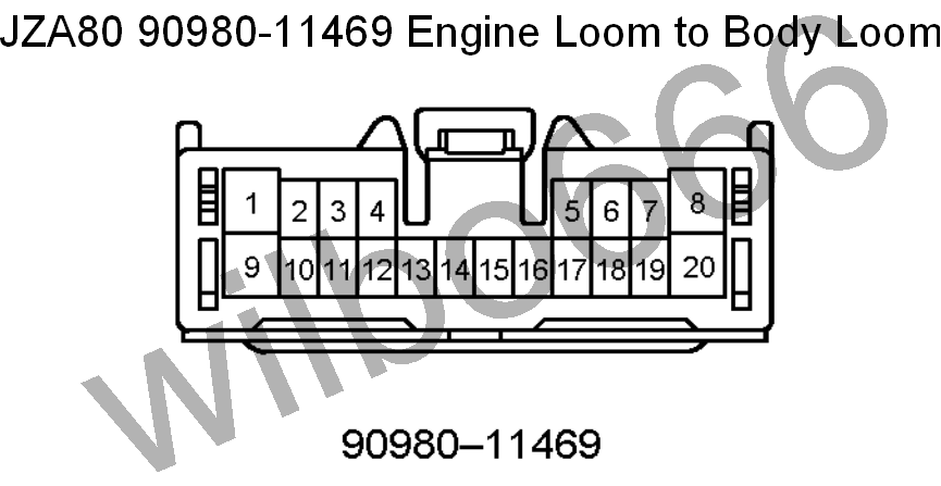
Note: Blue text indicates pins related to automatic transmission functions only.
| Pin | Symbol | Definition | Input / Output (To engine = Input) (From engine = Output) |
Description |
| 1 | |
Power to Coils and Igniter | Input | The body loom side of this pin needs to be connected to battery voltage via the ignition switch when the ignition is in the RUN and CRANK positions to switch battery voltage to the coils and igniter. The engine loom side of this pin connects to the coil and igniter power supply pins. |
| 2 | Engine Coolant Temperature Dash Sensor | Output | The body loom side of this pin is not connected. The engine loom side of this pin connects to the one wire engine coolant temperature sensor located at the engine coolant water outlet to the radiator on the front, upper, exhaust side of the engine. |
|
| 3 |
/ | / | / | / |
| 4 | Engine ECU: FPC Fuel Pump ECU: FPC |
Fuel Pump Control | Output | The body loom side of this pin needs to be connected to the fuel pump ECU FPC pin. The engine loom side of this pin is connects to the engine ECU FPC pin. |
| 5 | / | / | / | / |
| 6 | / | / | / | / |
| 7 |
Engine ECU: NSW (Engine ECU: STA) |
Neutral / Park Automatic Transmission Position Switch Indicator (Starter Motor Relay Trigger Signal) |
Input |
The body loom side of this pin needs to be connected to an ignition switched power source that supplies battery voltage when the ignition is in the CRANK Positions.
|
| 8 | / | / | / | / |
| 9 | |
Ignition Switched Power to Fuel Injectors | Input |
The body loom side of this pin needs to be connected to an ignition switched power source that supplies battery voltage when the ignition is in the CRANK Positions.
|
| 10 | Low Oil Pressure Switch | Output | The body loom side of this pin is not connected. The engine loom side of this pin connects to the low oil pressure switch located on the front, lower, intake side of the engine. |
|
| 11 | Engine ECU: STP | Stop Light Switch | Input | The body loom side of this pin needs to be connected to the switched side of the brake light switch. The engine loom side of this pin connects to the engine ECU STP pin. |
| 12 | Engine ECU: DI Fuel Pump ECU: DI |
Fuel Pump Diagnostic Indication | Input | The body loom side of this pin needs to be connected to fuel pump ECU DI terminal. The engine loom side of this pin connects to the engine ECU DI pin. |
| 13 | / | / | / | / |
| 14 |
Engine ECU: ABS
ABS ECU: EXO |
ABS | Input? | The body loom side of this pin connects to the ABS ECU EXO pin. The engine loom side of this pin connects to the engine ECU ABS pin. |
| 15 | Engine Mounted Diagnostic Connector: TS ABS ECU: TS |
Test Enable | Input | The body loom side of this pin connects to a number of control module 'TS' input pins. The engine loom side of this pin connects to the diagnostic connector mounted on the side of the engine TS pin. |
| 16 |
Engine Mounted Diagnostic Connector: WA
|
ABS | Input | The body loom side of this pin connects to the ABS ECU WA pin and also the ABS light mounted in the dash. The engine loom side of this pin connects to the diagnostic connector mounted on the side of the engine WA pin. Note that there is a shorting link inserted between terminals WA and WB of the engine mounted diagnostic connector. |
| 17 | / | / | / | / |
| 18 |
/ | / | / | / |
| 19 |
Engine Mounted Diagnostic Connector: OP4
Under Dash Mounted Diagnostic Connector: ABS
ABS ECU: D/G |
ABS | Input | The body loom side of this pin connects to the drivers side under dash diagnostic connector ABS pin and the ABS ECU D/G pin. The engine loom side of this pin connects to the diagnostic connector mounted on the side of the engine OP4 pin. |
| 20 |
/ | / | / | / |
JZA80 Toyota Supra 2JZ-GTE VVTi 90980-11562 Engine Loom to Body Loom Plug (White) [BC2]
This plug is located inside the passenger foot well and mates with male connector 90980-11561. (BC2).
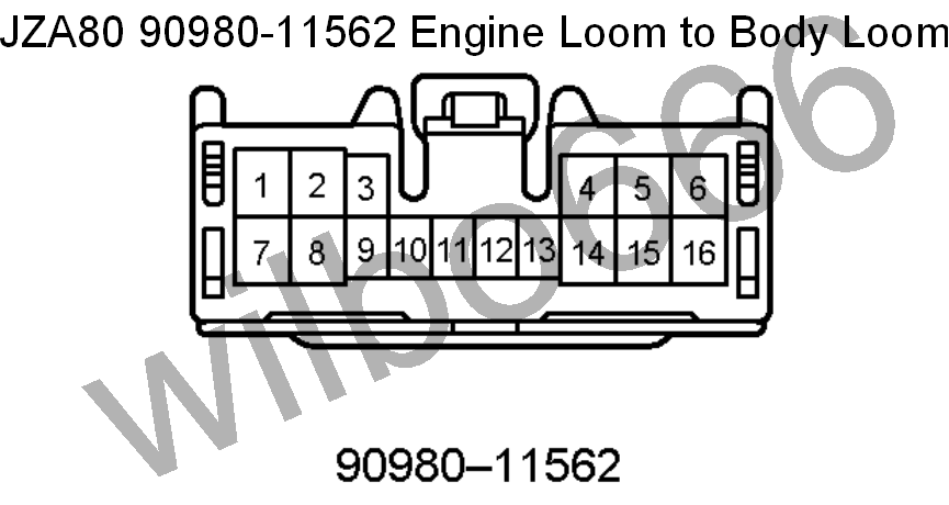
Note: Blue text indicates terminals related to automatic transmission functions only.
| Pin | Symbol | Definition | Input / Output (To engine = Input) (From engine = Output) |
Description |
| 1 | Engine ECU: SNWI |
Traction Control SNOW Mode Select Switch |
Input |
The body loom side of this pin connects to the traction control SNOW mode select switch.
The engine loom side of this pin connects to the engine ECU SNWI pin. |
| 2 | / | / | / | / |
| 3 |
|
Drive Gear Automatic Transmission Position Switch | Output |
The body loom side of this pin connects to the automatic transmission D/M shift selector switch. The engine loom side of this pin connects to automatic transmission shifter position switch mounted on the automatic transmission and outputs battery voltage when the automatic transmission shifter is in the D position. |
| 4 |
Engine ECU: SIL
Under Dash Mounted Diagnostic Connector: SIL
|
OBDII |
Output |
The body loom side of this pin connects to the drivers side under dash diagnostic connector SIL pin. The engine loom side of this pin connects to the engine ECU SIL pin. |
| 5 |
Engine ECU: FRO
ABS ECU: FRO |
Front Right Wheel Speed | Input |
The body loom side of this pin connects to the ABS ECU FRO pin.
The engine loom side of this pin connects to the engine ECU FRO pin. |
| 6 |
Engine ECU: FLO
ABS ECU: FLO |
Front Left Wheel Speed | Input |
The body loom side of this pin connects to the ABS ECU FLO pin.
The engine loom side of this pin connects to the engine ECU FLO pin. |
| 7 |
Engine ECU: TC
Engine Mounted Diagnostic Connector: TC
|
Test Connector | Output |
The body loom side of this pin connects to the drivers side under dash diagnostic connector TC pin and pin 11 of body plug GC2-11 which connects to pin 21 of body plug 90980-11555.
The engine loom side of this pin connects to the engine ECU TC pin.
Refer to pin 21 of body loom plug 90980-11555 for further information.
|
| 8 | Engine ECU: EC |
Ground |
Input |
The body loom side of this pin needs to be connected to Ground for the PRE and PRE2 switches Ground.
The engine loom side of this pin connects to the engine ECU EC pin. |
| 9 | Engine ECU: E1 | Ground | Output | The body loom side of this pin connects to the ground for the steering wheel mounted, automatic transmission gear switch assembly. The engine loom side of this pin connects to the engine Ground at the intake manifold. |
| 10 | Engine ECU: SFTD |
Automatic Transmission Shift Down | Input | The body loom side of this pin connects to the steering wheel mounted, automatic transmission down gear switch. The engine loom side of this pin connects to the engine ECU STFD pin. |
| 11 | Engine ECU: SFTU | Automatic Transmission Shift Up | Input | The body loom side of this pin connects to the steering wheel mounted, automatic transmission up gear switch. The engine loom side of this pin connects to the engine ECU STFU pin. |
| 12 |
Engine ECU: MSW |
Traction Control OFF |
Input |
The body loom side of this pin connects to the traction control off switch.
The engine loom side of this pin connects to the engine ECU MSW pin. |
| 13 | / | / | / | / |
|
14 |
Engine ECU: RSPD |
Road Speed Signal? |
Output |
The body loom side of this pin connects to the shift lock control ECU.
The engine loom side of this pin connects to the engine ECU RSPD pin. |
| 15 |
Engine ECU: RRO
ABS ECU: RRO |
Rear Right Wheel Speed | Input |
The body loom side of this pin connects to the ABS ECU RRO pin.
The engine loom side of this pin connects to the engine ECU RRO pin. |
| 16 |
Engine ECU: RLO
ABS ECU: RLO |
Rear Left Wheel Speed | Input |
The body loom side of this pin connects to the ABS ECU RLO pin.
The engine loom side of this pin connects to the engine ECU RLO pin. |
JZA80 Toyota Supra 2JZ-GTE VVTi 90980-10897 Engine Loom to Body Loom Plug [BA1]
This plug is located inside the engine bay near the battery and mates with male connector 90980-10896. (BA1).

| Pin | Symbol | Definition | Input / Output (To engine = Input) (From engine = Output) |
Description |
| 1 | AC Magnetic Clutch | Input | The body loom side of this pin needs to be connected to the AC magnetic clutch relay switched power output which switches battery voltage to the AC magnetic clutch to energise the clutch and turn the AC on. The engine loom side of this pin connects to the AC magnetic clutch. The AC magnetic clutch is grounded via the engine block. |
|
| 2 | Engine ECU: ACMG | Air Conditioning Magnetic Clutch Relay Trigger Signal | Output | The body loom side of this pin needs to be connected to the AC magnetic clutch relay coil negative. The engine loom side of this pin connects to the engine ECU ACMG pin. |
| 3 |
Engine ECU: STA (Engine ECU: NSW) |
Starter Motor Relay Trigger Signal | Output | The body loom side of this pin needs to be connected to the starter motor relay coil positive to turn the relay on when the ignition switch is in CRANK position (and the automatic transmission park / neutral switch is in the park / neutral position if the vehicle is equipped with an automatic transmission). Manual transmission: The engine loom side of this pin is connected in the engine wiring loom to the engine ECU STA pin, the engine ECU NSW pin and pin 7 of the engine loom to body plug 90980-11469. Automatic transmission: The engine loom side of this pin is connected to the automatic transmission park / neutral position switch and also the engine ECU STA pin. Refer to pin 7 of body loom plug 90980-11469 for further information. |
| 4 | Engine ECU: BATT | Battery Power | Input | The body loom side of this pin needs to be connected to constant battery voltage. The engine loom side of this pin connects to the engine ECU BATT pin. |
| 5 | / | / | / | / |
| 6 | Engine Mounted Diagnostic Connector: WB | ABS | Output | The body loom side of this pin connects to the ABS actuator W pin. The engine loom side of this pin connects to the diagnostic connector mounted on the side of the engine WA pin. Note that there is a shorting link inserted between terminals WA and WB of the diagnostic connector from factory. |
| 7 | / | / | / | / |
| 8 | Engine ECU: M-REL | EFI Main Relay Trigger Signal | Output | The body loom side of this pin needs to be connected to the main EFI relay coil positive. The engine loom side of this pin connects to the engine ECU M-REL pin. |
JZA80 Toyota Supra 2JZ-GTE VVTi 90980-11413 Engine Loom to Body Loom Plug [BA2]
This plug is located inside the engine bay near the battery and mates with male connector 90980-11421 (BA2).

| Pin | Symbol | Definition | Input / Output (To engine = Input) (From engine = Output) |
Description |
| 1 | Starter Motor Relay Switched Power | Input | The body loom side of this pin needs to be connected to the starter motor relay switched power output which switches battery voltage to the starter motor to turn it on and crank the engine. The engine loom side of this pin connects to the starter motor solenoid. The starter motor is grounded via the engine block. |
|
| 2 | Engine Mounted Diagnostic Connector: +B |
Main EFI Relay Switched Power | Input |
The body loom side of this pin needs to be connected to the main EFI relay switched power output which switches battery voltage to the VSVs, oxygen sensor and the engine mounted diagnostic connector +B pin. The main EFI relay is switched via the engine ECU M-REL output pin.
The engine loom side of this pin connects to the engine ECU, VSVs and AFM power supply pins. |
| 3 | Engine ECU: +BM | ETCS-i Power | Input |
The body loom side of this pin needs to be connected constantly to the battery via a 15A fuse.
The engine loom side of this pin connects to the engine ECU +BM pin. |
| 4 | Alternator: S |
Alternator Battery Voltage Sense | Input |
The body loom side of this pin needs to be connected constantly to the battery via a 7.5A fuse.
The engine loom side of this pin connects to the alternator S pin. |
| 5 | Engine ECU: +B, +B1 | Main EFI Relay Switched Power | Input |
The body loom side of this pin needs to be connected to the main EFI relay switched power output which switches battery voltage to the engine ECU, VSVs and AFM. The main EFI relay is switched via the engine ECU M-REL output pin. |
JZA80 Toyota Supra 2JZ-GTE VVTi Wiring Diagrams
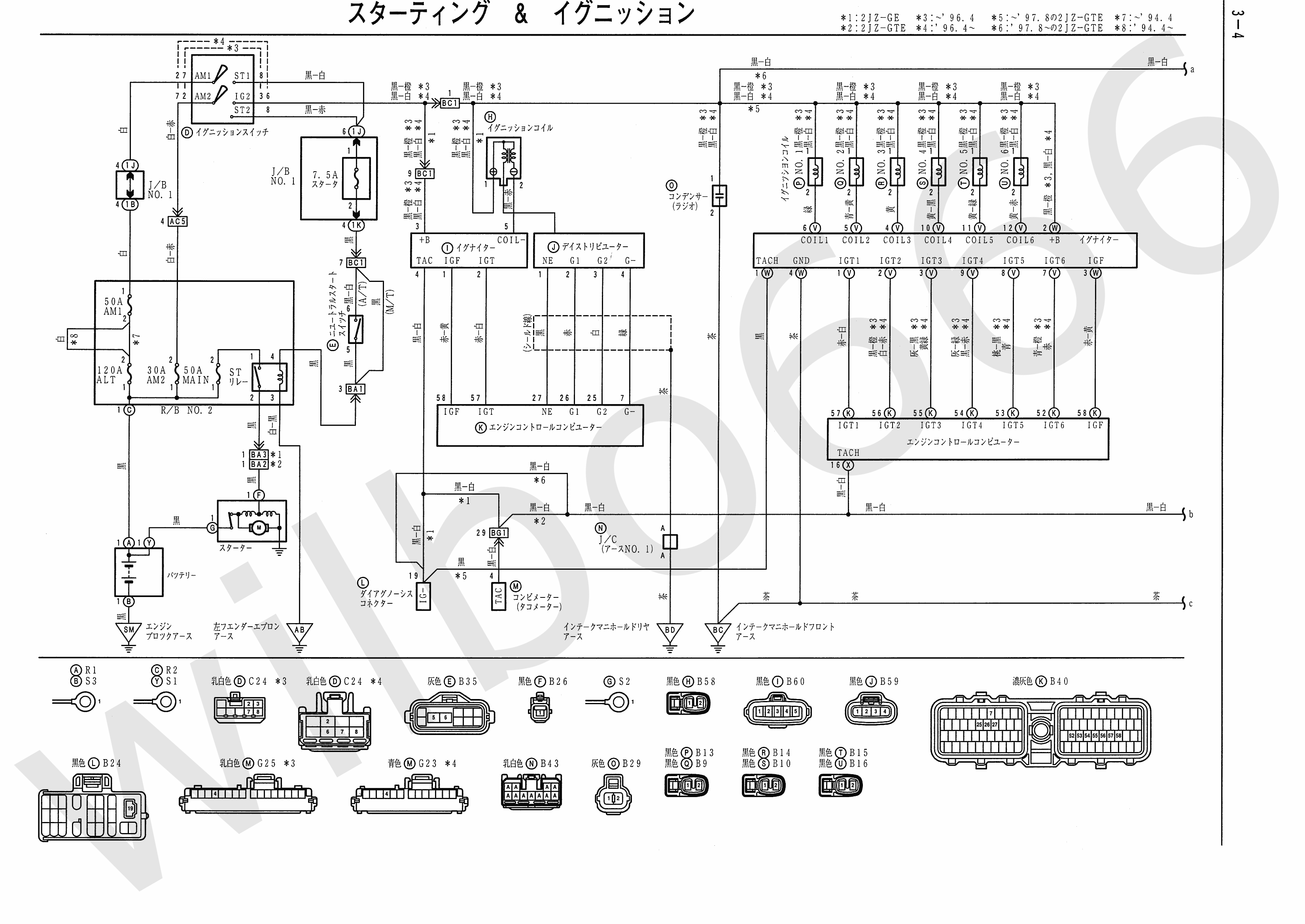


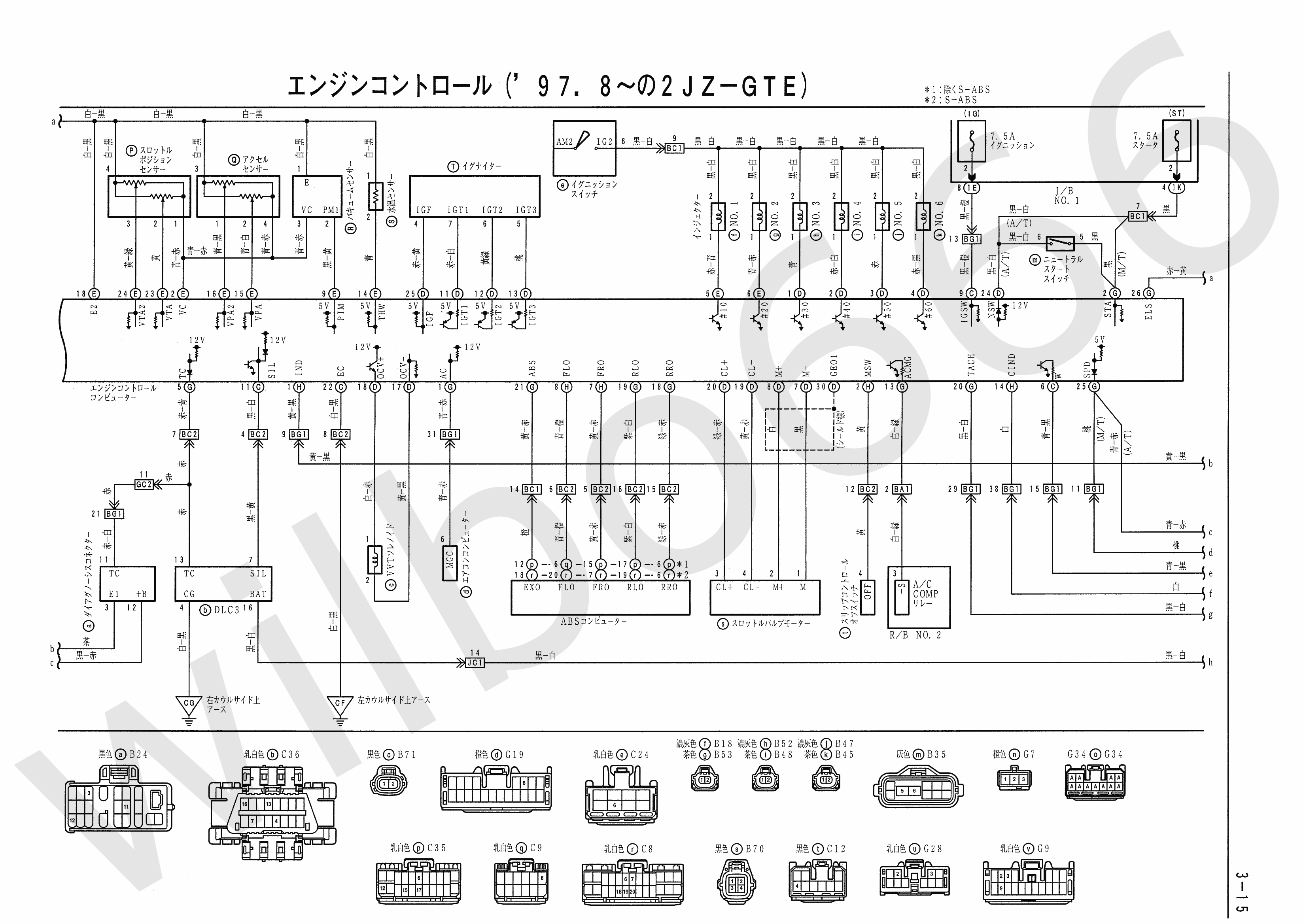
JZA80 Electrical Wiring Diagram Book 6742505
JZA80 Electrical Wiring Diagram Book 6742505.pdf
Views: