Introduction
This page documents Toyota air flow sensors, often refereed to as AFM (Air Flow Meters) or MAF sensors (Mass Air Flow).
There are a number of different types of Toyota air flow sensors, including the older 'flap' style, Karman vortex and hot wire to name a few.
In general air flow meters are used to detect the mass of air that is entering an engine so that the correct amount of fuel can be injected. Internal combustion engines have a requirement for a specific ratio of air to fuel which is called the Air Fuel Ratio or AFR. If the air flow is measured then the required fuel can be calculated and then injected.
As the density of air changes across temperature it is logical to include an air temperature sensor as part of the air flow sensor so that the mass of air can be determined (it is the mass of air not the volume that is required for correct AFR calculations).
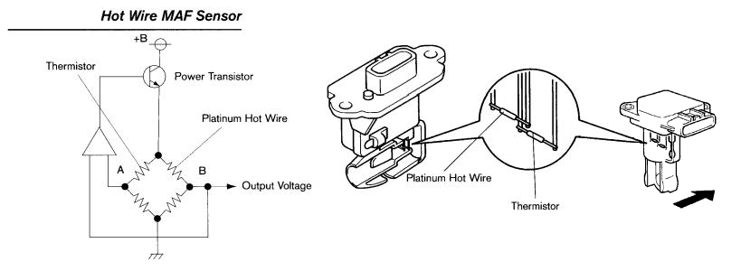
Hot Wire Mass Air Flow Sensor (5 Wire)
Operation of a hot wire MAF according to DENSO (a manufacture of Hot Wire MAFs) :
"A portion of the intake air from the air cleaner is bypassed into the hot-wire measurement area, where the intake airflow volume is measured. The hot-wire type MAF Sensor responds to temperature changes in the heating element. Changes in the resistance value and current of the heating element are converted into proportional voltage in the control circuit, and then sent to the ECU to calculate the amount of engine intake air volume."
This style of MAF comes in a number of different packages.

| Pin |
Symbol |
Definition |
Input / Output
(To Sensor = Input)
(From Sensor = Output) |
Description |
| 1 |
THA
|
Air Temperature Sensor |
Output
|
This pin connects to a thermistor that is installed in the airflow sensor and outputs a voltage related to the air temperature to the engine ECU.
|
| 2 |
E2 |
Sensor Ground |
Input |
The airflow meter has a separate power ground to ensure clear signals. This pin is connected to sensor Ground inside the engine ECU. |
| 3 |
EVG |
Airflow meter signal ground. |
Input |
The airflow meter sensor has a separate signal ground to ensure a clear signal. This pin is connected to sensor Ground inside the engine ECU. |
| 4 |
+B |
EFI Main Relay Switched Power |
Input
|
This pin supplies power to the airflow meter. This pin is connected to battery voltage (+12V) when the Main EFI Relay is energised via the engine ECU pin M-REL pin.
|
| 5 |
VG |
Engine Airflow |
Output |
This pin connects to the signal output of the airflow sensor and output a voltage related to the airflow to the engine ECU. |
References
http://en.wikipedia.org/wiki/Mass_flow_sensor
http://www.denso-am.eu/products/automotive-aftermarket/engine-management-systems/mass-air-flow-sensors/how-they-work/
Views: 
Comments (0)
You don't have permission to comment on this page.